Cluster Tool recognition with Predefined Cluster Tool
Cluster Tool Type for Recognition
This tutorial introduces you to a basic procedure in using cluster tool recognition.
In Image2Punch Pro version 6.0.0 and above, the type of cluster tool that can be used are as below. These types of cluster tool are predefined tool in Image2Punch: 2 X 2, 3 X 3, 4 X 4, 2 X 3 ( Horizontal and Vertical), 2 X 3 Staggered ( Horizontal and Vertical) and 1 X 4 ( Horizontal and Vertical).

Defining and Creating a Cluster Tool Type
You need to define and create the cluster tool in Image2Punch. For example you have a 4 X 4 Cluster tool with center-to-center distance is 10mm and the tool diameter is 6mm. We also define the diameter of cluster tool center by using 0.75mm. This hole is very important to mark the position of cluster tool.

Defining the Minimum Gap for Pattern
The next step is to calculate the minimum gap for the pattern. Since we want to use 4 X 4 Cluster tool we have specified and created on the previous step, the minimum gap ( between edge to edge) will be 10mm – 6mm = 4.0mm.
Defining the Tools for Pattern
In this step, the biggest tool must be similar to the cluster tool. in this case the biggest tool will be 6.0mm. For the other tool that you want to use, it does not matter for the quantity or the size as long as smaller than 6.0mm. For the purposes of this tutorial, i will be using 3 tools: they are 6.0mm, 5.0mm and 3.0mm.

Selecting Cluster Tool for Pattern Generation
Now we have setup all parameter to generate the pattern. Since we use 4 X 4, the pattern type will be rectangular pattern. Then we click the CLUSTER RECOGNITION OFF Button, to define the cluster tool that will be used for this pattern. In this case we will use Cluster 4 X 4 CTRS 10mm Dia 6.0mm. After selecting the cluster tool and defining the recognition area, we close the dialog box and we can see that the button will say CLUSTER RECOGNITION ON. After that we can now click the generation button to generate the pattern.

As you can see on the cluster recognition dialog box, there is an area where you can define the segmentation during the recognition. This segmentation will helps to make the calculation faster by dividing into smaller segments. for example we can make the horizontal and vertical segmentation segmentation in value of 2. However the drawback using segmentation is that the total tool that ware recognized will be smaller as the area had been segmentated. Therefore a good rule of thumbs is using segmentation only for a large pattern which consist of more than 100K tool hits.
Selecting Cluster Tool for Pattern Generation
Now we have setup all parameter to generate the pattern. Since we use 4 X 4, the pattern type will be rectangular pattern. Then we click the CLUSTER RECOGNITION OFF Button, to define the cluster tool that will be used for this pattern. In this case we will use Cluster 4 X 4 CTRS 10mm Dia 6.0mm. After selecting the cluster tool and defining the recognition area, we close the dialog box and we can see that the button will say CLUSTER RECOGNITION ON. After that we can now click the generation button to generate the pattern.

As you can see on the cluster recognition dialog box, there is an area where you can define the segmentation during the recognition. This segmentation will helps to make the calculation faster by dividing into smaller segments. for example we can make the horizontal and vertical segmentation segmentation in value of 2. However the drawback using segmentation is that the total tool that ware recognized will be smaller as the area had been segmentated. Therefore a good rule of thumbs is using segmentation only for a large pattern which consist of more than 100K tool hits.
Saving the DXF as result of the pattern.
After you satisfy with the result, you can then save the pattern into a DXF file. Then this DXF file will be use as an input for tooling process by using your CAM software ( i.e. JETCAM, CADMAN or Sigmanest for Turret Punch).
Before saving the DXF, please ensure that All the two important parameter for cluster tool has been ticked on. They are: Enable Cluster Tool Center and Enable Layer System.
After that two had been ticked, you can then saved the pattern into a DXF file. Then open it on your CAM Software.

Modify the DXF for CAM tooling
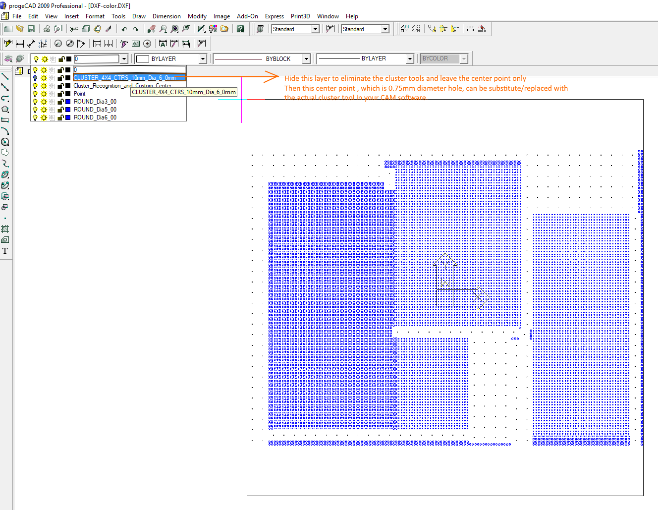
In this step, you need to hide or delete the cluster tool but leave the center point. You can do this by using autoCAD or any CAD software that can read DXF file format including the layer system. If you are using AutoCAD, you can then hide the layer that contain the cluster tool. Or even you just delete all the cluster tool in that layer. And the final DXF will be the single tools and the center point of the cluster tool as illustrated below.

CAM Software as the Next Step
After that, you open the modified DXF that consist of the single tools and the center point of the cluster tools. Most of CAM software will have a feature to make automatic punch tool selection for hole. after the automatic selection process done, then you need to replace for all 0.75mm diameter ( which is the center point of the cluster tool) by using your cluster tool. And finally you create a G code for your CNC Punch machine.


