Image2Punch Step By Step Tutorial 2
Getting Started
In this tutorial I will try to give step-by-step instructions on how to use Image2Punch to generate a common perforated pattern. Rather than creating a new image, I will use an existing image. Then defining and selecting the tools that I will use to generate the pattern. After that, I will select and change some parameter to suit the requirement of the pattern according to specification. Lastly, I will save the pattern into a DXF file.
In order to create this tutorial, I use Image2Punch Pro version 7.0.0. However, the principle and procedure in this tutorial can also be applied for Image2Punch Genesis and Image2Punch Lite.
If Image2Punch isn’t already running, start it now. You can do this either by double clicking on the Image2Punch icon on your Windows desktop or by selecting the Image2Punch menu item on its folder from the Windows Start button.
In the case that Image2Punch program give a runtime error, please run as Run As Administrator Mode. In order to enable this, user need to right click the Image2Punch Icon, then select “Run As Administrator” as in the Figure 1. If the user need to continue to run it as administrator, he or she need to click the property and select the compatibility tab. Then check the “Run this program as an administrator as illustrated in the Figure 2.

Figure 1
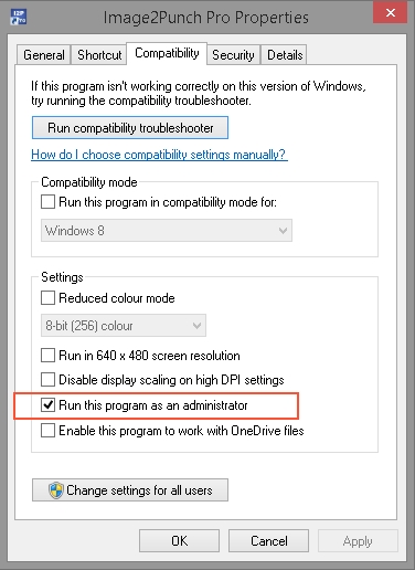
Figure 2
Open an Existing Image and Image Quality
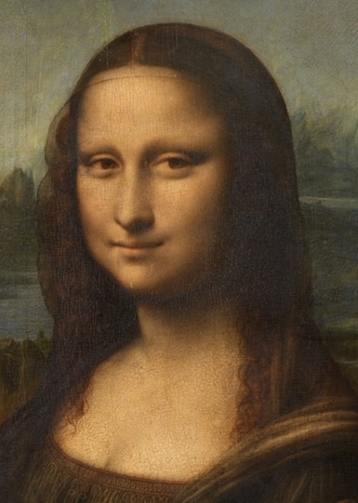
The image I have prepared and cropped is a portrait of Mona Lisa painting by Leonardo da Vinci. I downloaded the image from https://commons.wikimedia.org/wiki/File:Leonardo_da_Vinci_-_Mona_Lisa.jpg. This photograph is in public domain and I believe I can use it as an example for this tutorial.
The cropped size of the image for this tutorial is 600pixel wide and 427pixel High.
Image2Punch can open a larger image file size but the maximum will be capped into 10000pixel wide and 10000pixel high. The reason for this restriction is to save memory during the calculation. Also, in generating perforated pattern, the software does not need very large file. For example, if we want to generate a rectangular pattern that has 1000 holes in horizontal and 1000 holes in vertical, we only need an image that has the size of 1000pixel X 1000pixel. effectively the total holes will be 1 million which is a massive number of punch strokes for CNC Turret Punch.
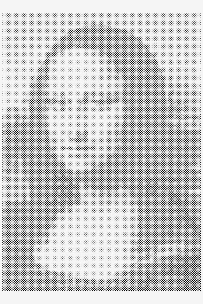
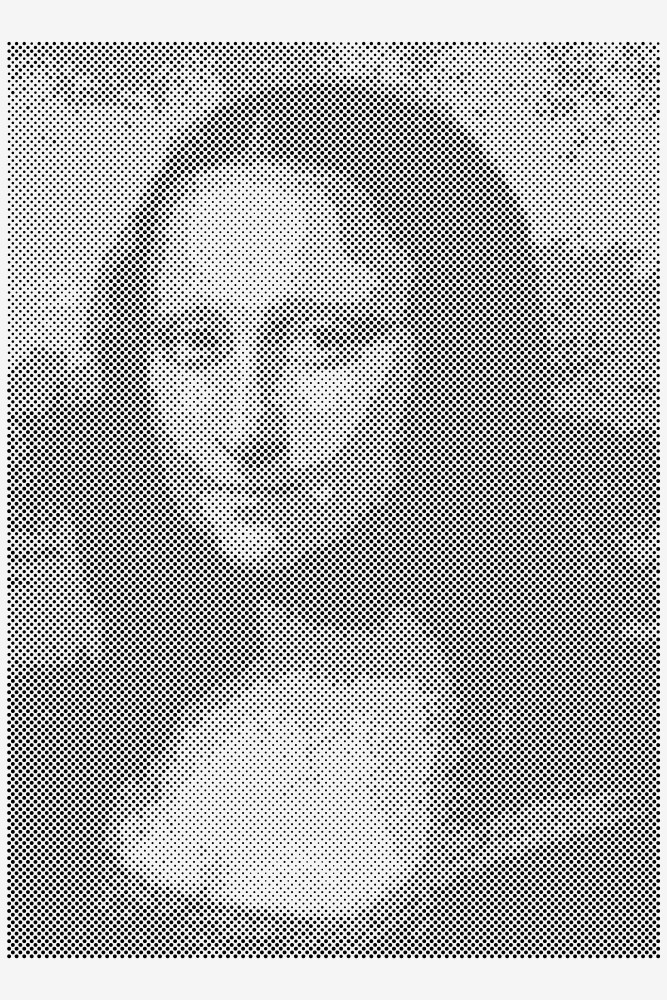
On the other hand, the quality of image regarding the pixel information will be very important. For example these two images below have similar image size (600 x 427), but the pixel information on the left hand is hugely better than the one on the right hand side. Therefore, the pattern result from the left hand side of image (before image) will give a better pattern than the one on the right ( after image).
You can examine by dragging the scrolling to see these two images.

In order to open an image file, please select the File Menu and click Open. You can also do this by clicking the Open Image Icon (blue icon) on Standard Toolbar.

Image Editing Process
In most cases, after the image is open, we can go straight to the Tooling Phase. However, there are few moment that we probably need to use the image manipulation feature available in Imaging Phase. The most common tool that I use to do some minor adjustment is cropping. In another case, I also use Color Stretch and/or Equalization to balance the color so the pattern can be better reflect the original image.
If you want to know all these image manipulation effect, please have a look into the Manual Help Instruction in Imaging Design Phase chapter.
For the purposes of this tutorial, I will just use the image as is without any image processing required.

Configuring Setting Preference
In this step, we need to determine an important setting parameter, which is the unit measurement for the current document. You can select either in inch or mm. Then all other dimension will be calculated and converted to the unit measurement that you have selected.
We can also determined how the perforated pattern holes are saved in DXF file format. In this general setting parameter, we can also select either to enable or disable the warning during the processing and calculating the perforated pattern.
For this tutorial, The System Unit will be in mm. For the CAD Output Preference, I want to have the sheet size rectangle and all holes will have its center point. Then I also enable the Cluster Tool Center and so the layer system as well as the tool hit color. By enabling the last two, the pattern will be saved where each type of the hole will be allocated in their own layer. And the layer color will reflect each tool color.
For all the warnings, I just leave as per illustration below. If you want to know more regarding the setting preference, please find out from Manual Help Instruction.
To open the Setting Preference dialog box, please go to File Menu and then click the Setting preference item.

Generating Tool for Tool Database Library
For the first time user of Image2Punch, This step is to create and generate the tooling database that represent the available punching tool in your workshop.
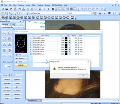
To create a new tool, user need to define the tool type, then select the icon that represent the tool type. For example, If we want to create 3.0mm Diameter circle tool, we click the round tool icon to open the round tool Database dialog box. Then, Click Add to create a new Round Tool. When an instance is created, it will show a unique tool name with default information for diameter, station, color and unit measurement. Then user need to change or modified the tool according to the requirement. For example, The Tool Name will be ROUND R1.50 with the diameter 3.0 and the unit is mm by ticking the button.

In the end, I have created 8 round tools ranging from 1.0mm diameter to 6.0mm diameter which will be used in generating the perforated pattern for this tutorial.
Perforated Pattern Design Specification
The next step is to define the specification for the perforated pattern. In this case, we will use 0.75mm Aluminium with the size of 1000mm wide and 1500mm high. The pattern will be 45 degree angle pattern. This pattern will be used to create a normal perforated sheet without backlight for Company Logo display. This mean that the background will be light color (white) and the holes will be darker color (black).
As we use 0.75 mm Aluminum thick, it is wise if we use larger gap between the hole. I will plan to have 2.0mm minimum gap in between the holes. I also design that the minimum gap border for all the edge of the sheet will be 10mm.
From this point, you can change the minimum gap and the border parameter to your specification. Please note the minimum gap should not be smaller than the material thickness. In many cases, it is better that the minimum gap as least two times larger than the material thickness.
Configuring Perforated Pattern parameters
After we know the perforated pattern specification, we can now configure and setup the parameter for generating the pattern in Image2Punch. In doing so, we need to go to Tooling Design Phase by clicking the Tab Button in the Navigator Bar. Then we specify all the information defined in previous step.
In the illustration below, The sheet size, material thickness and type as well as the border parameter has been defined and selected. The Normal Tool Order is specified as the pattern will be used for normal display without the backlight. (i.e. The hole will be darker color and the material is lighter)

After configuring the material, the next thing is to select the perforated pattern type. To open the dialog box, please click the first button in Perforate Type Group. Then click the Angle Tab to select the angle pattern. Position the slide bar to 45 as we will use 45 degree angle pattern for this tutorial.

Selecting Tool for Perforated Pattern
After we define the sheet size and perforated pattern type, the next important thing is to select tools. In this tutorial, I select all tools in between 1.0mm diameter and 6.0mm diameters. Please note, the smallest tool should not be smaller than material thickness and it is a good idea to use 1.0mm diameter when using 0.75mm thick material for the perforated pattern.
There are no precise rule in selecting the largest tool for the perforated pattern. Most of the time I will select the largest tool that is around 4 or 5 times larger than the smallest tool. However this is only a guidance as there will be many factor in selecting the tool size. Another point to note is that the bigger the tool, the lesser the resolution of the pattern.
Because we are using Turret Punch to manufacture the pattern, we need to ensure that the second button in Tool Selection area will state Punch Mode Tooling. However if we want to manufacture the perforated sheet using CNC Laser, we need to click again so the button will state laser Mode Tooling. This second button will determine what kind of dialog box that will come out when selecting the tool.

Method to Calculate the Image
After the tool selection is done, The next thing is to define how the image is translated into the perforated pattern. First of all, we need to tick the Neighboring Pixels so the calculation pixel will not be one pixel, but also calculates the surrounding pixel on that particular location.
The last parameter that we need to have a look is Data Range Classification. This configuration will determine the relationship between the pixel calculation and the characteristic of the tool. For example the pixel value will be scaled between 0 and 1 and it could be any value in between. If we select the first option, This mean that the largest pixel value will be related to the top selected in the list. If we select the second option, it means that the largest pixel value will be related to the largest diameter of the selected tool. For more information regarding Data Range Classification, user can look up into the instruction Manual. For the purposes of this tutorial, i will select the first option.

Pattern Generation and Result Viewing
After the tool selection is done, we can finally press the Generate Button down at the bottom of Navigator bar. In order to check and viewing the pattern better and larger, The user may use the zooming, panning and pattern viewing model option.

As the viewing area has been optimized for speed and performance, displaying of perforated pattern result on the screen has been simplified. In order to display the pattern in for better viewing, I normally click the Print Preview Button which will be presented in better image rendering process.

In the case the pattern result need to be modify, user can change the configuration and changing the tool selection, the click the Generate button again to regenerate the pattern based on modified configuration.
Iteration for Better Result
After we have the suitable perforated pattern, we can then save it into a DXF file. However, we may try several configuration to get the best perforation result.
There are many ways to improve the final pattern result which can described as below.
- Acquiring better Image and conducting image manipulation. When you can get a better image that show many details, the pattern result could improve. If you cannot get a better quality image, you can always trying to improve it by implementing image manipulation to make stronger contrast, to highlight some darker part of image. Or perhaps you can implement the Color Stretch or Equalization image manipulation in Image2Punch. ( please see point no.3 above). The illustration below shows the original image on the left hand side and the result after Equalization image manipulation is applied. The effect is to distribute the color evenly and make the image have better brightness
- Changing the formation for the selected tool. In this tutorial (image on the left hand side), I use 8 tools ranging from 1.0mm diameter to 6.0mm diameter. Perhaps by changing the minimum and maximum diameter and adding more tool will give a better result. For example (image on the right hand side) I use 15 tools ranging from 1.5mm diameter to 9.0mm diameter with the same other configurations.


- Playing with Data Range Classification. In Point 9, You can select the way the image data is grouped and by changing the parameter of this option, you can perhaps get a better result of the perforated pattern. The images below will show you the different when you select option 1, 2 and 3 which calculated based on the equal averaging area, tool perimeter proportion and tool area proportion respectively.


